|
|
|
| FLOOR AND MAIN BEAM SYSTEM |
| SPECIFICATIONS |
 |
| |

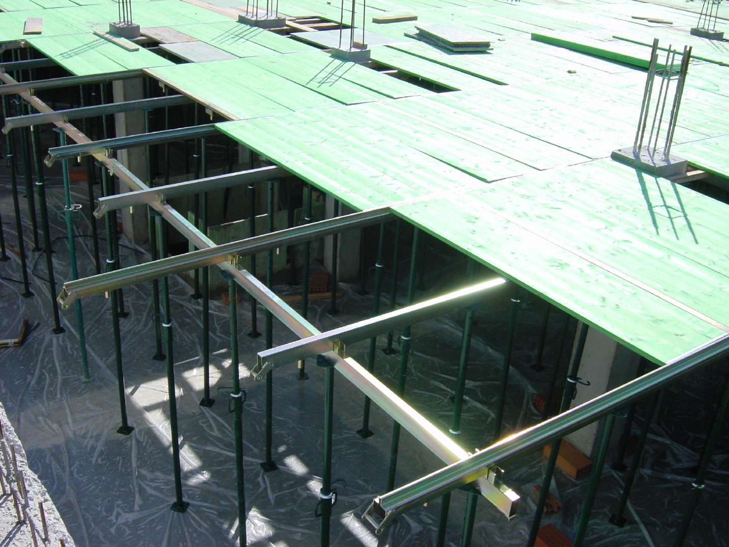
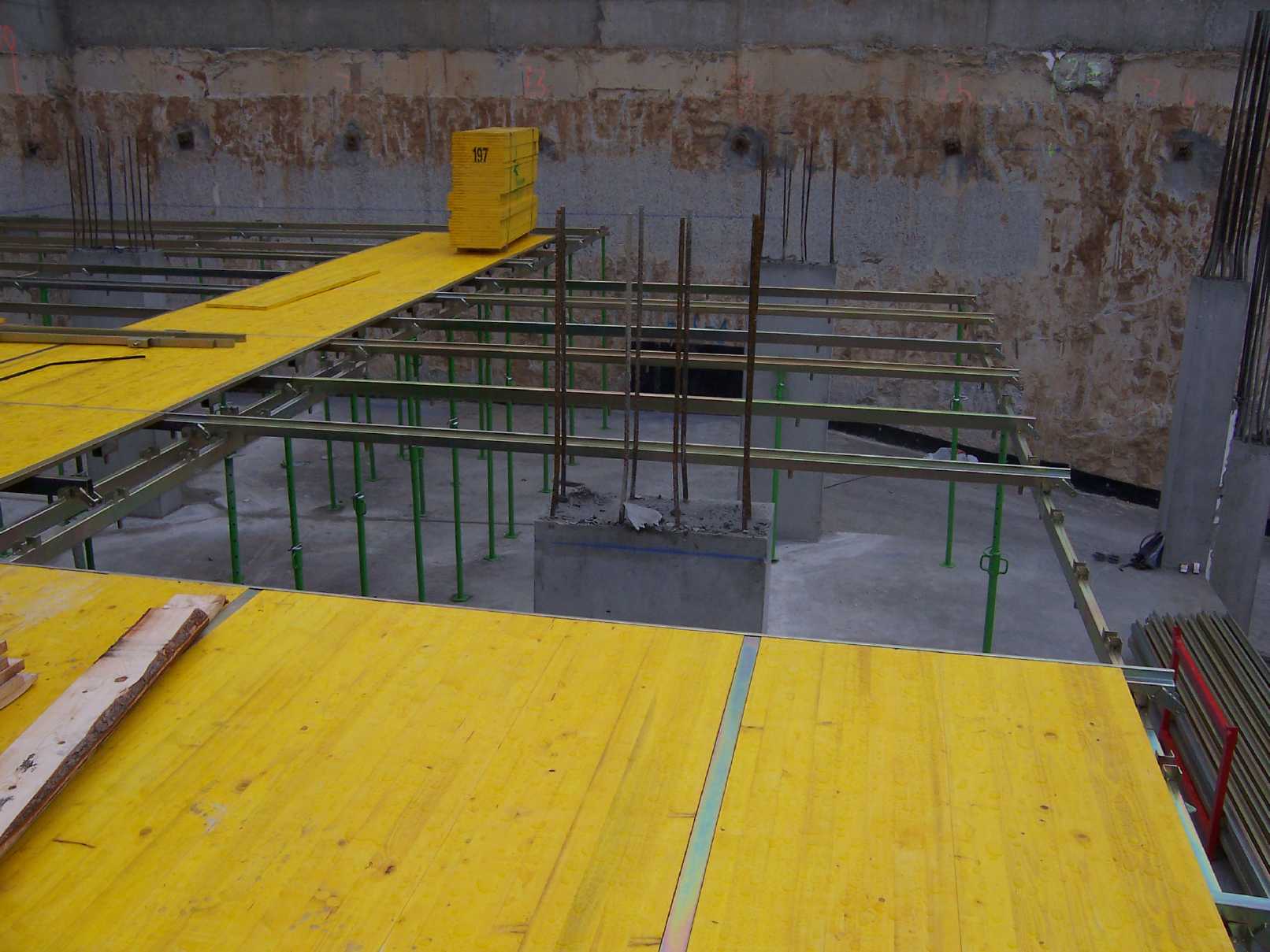
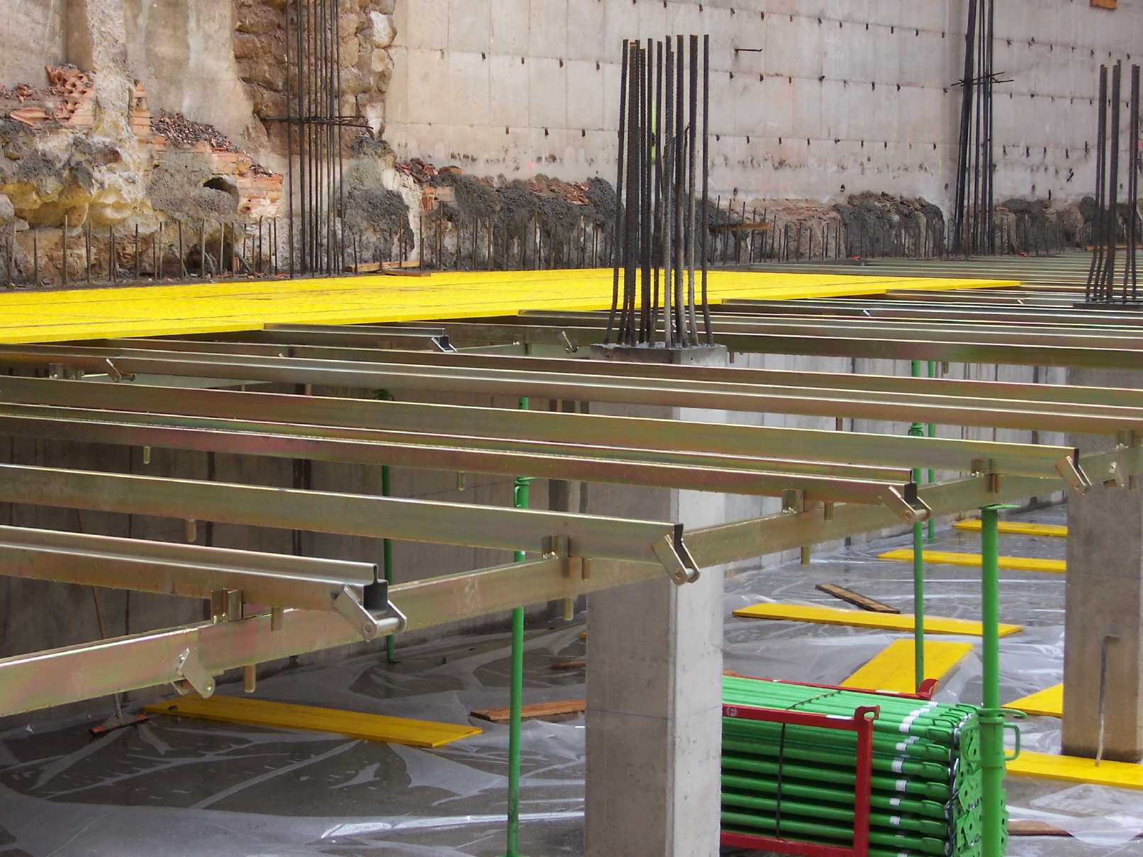
The floor and main beam system is designed for an easy adaptation to any building site configuration. This system allows the situation of the wood panels on the floor, with large dimensions parts saving working labour costs. The assembly and dismantling of the system is very quick and easy. You can also form main beams with this system and special accessories. Most parts are common for floor and main beam systems making it extremely polyvalent. All its parts are Zinc treated protecting the system against oxidation. |
| MODELS |
 |
 |
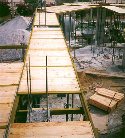
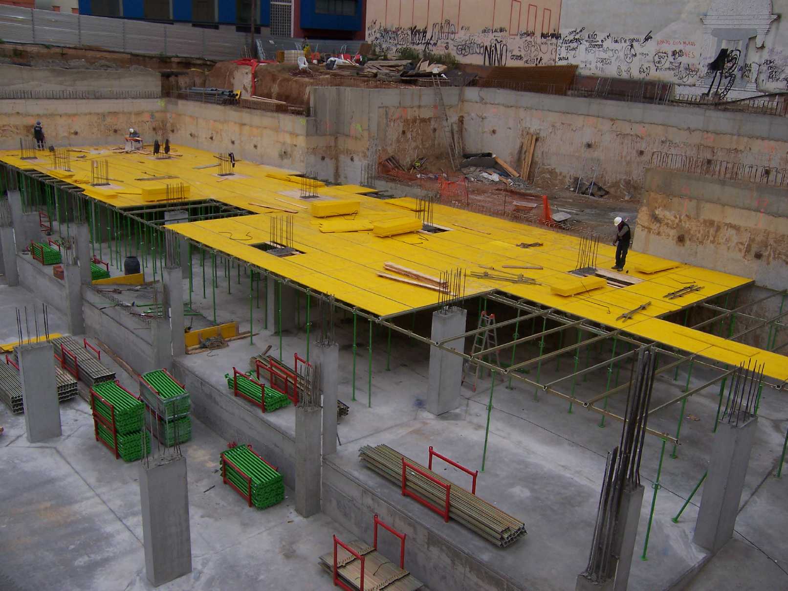
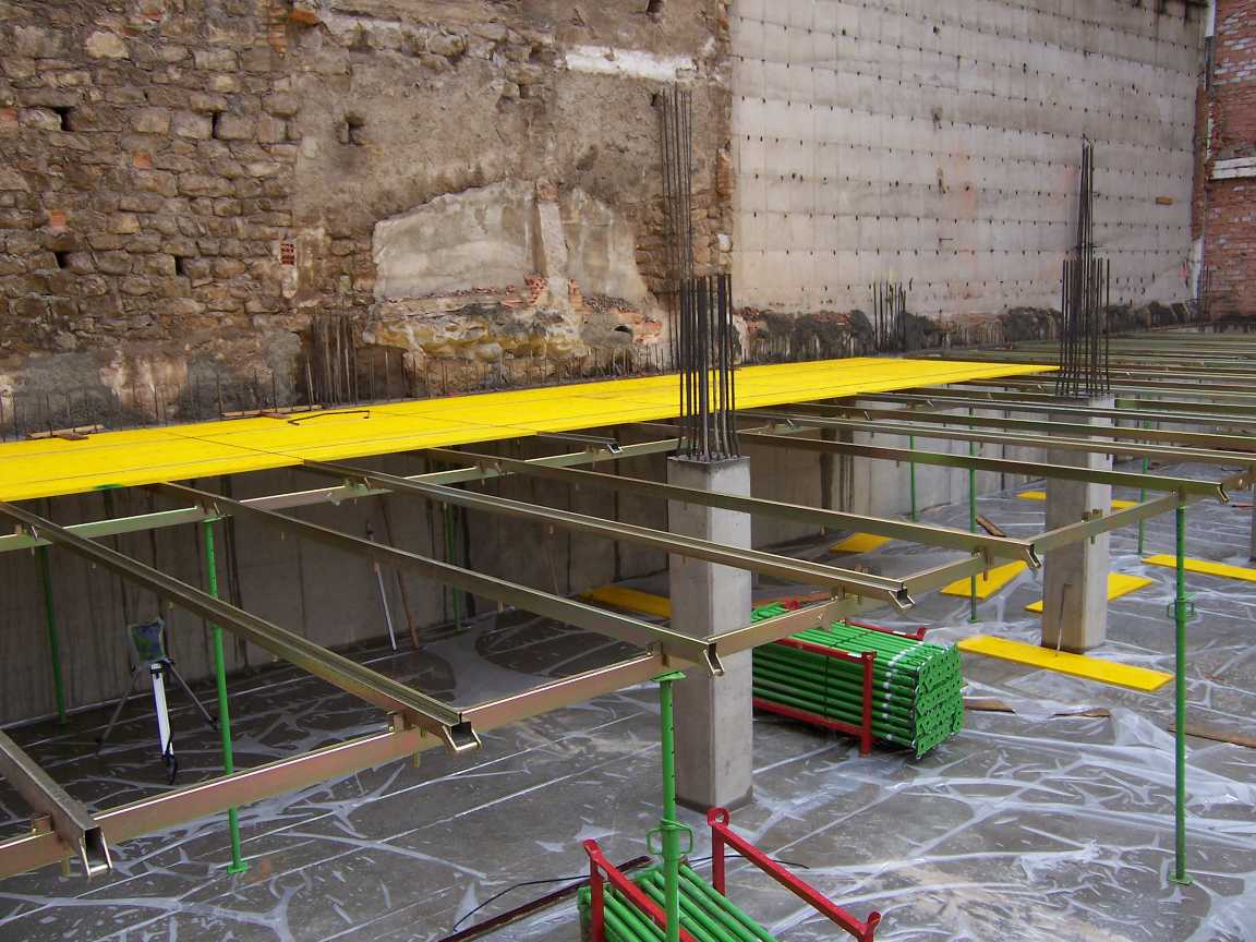
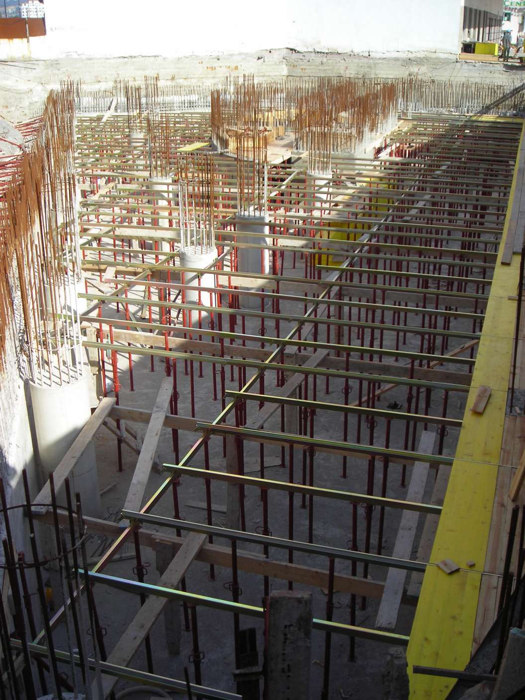
Floor System
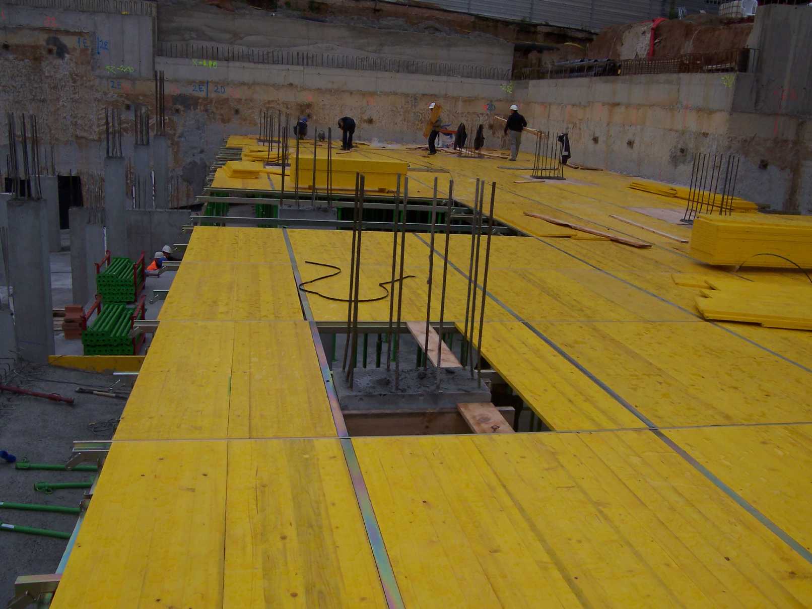
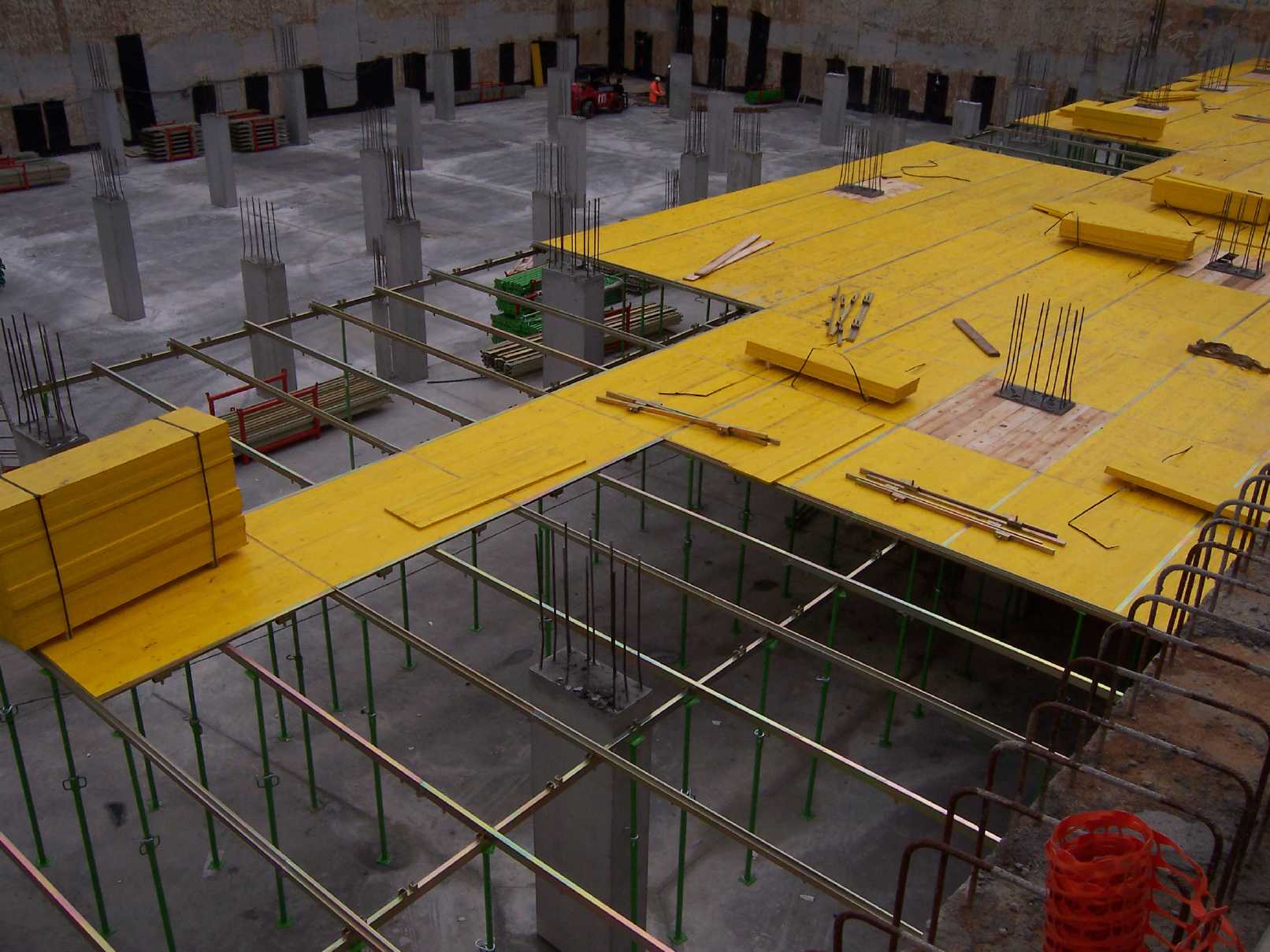
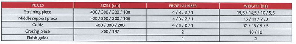
The floor system is specially designed to place the wood panels on all the building site area to work on it safely. Four main parts compose the system: Straining Pieces, Middle Support Pieces, Guides and Crossing Pieces. The Straining Piece, with its closing profile, is where we fit the wood panels. The Middle Support Piece is situated between the Straining Pieces reinforcing the system. The Guide shapes the entire grid. In the Guide we will shape the Straining Pieces and Middle Support Pieces. The Crossing Pieces will support all the structure after all the plant has been formed, recovering 85% of the element of all the structure, supporting the weight of all the structure. We fit one Crossing Piece every three wood panels |
|
|
 |
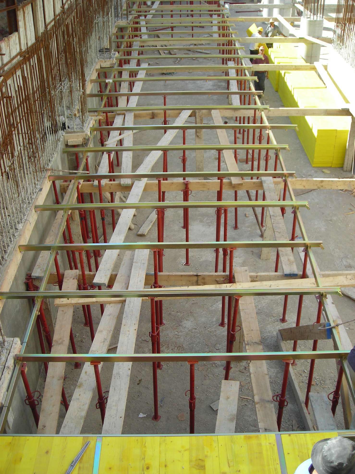
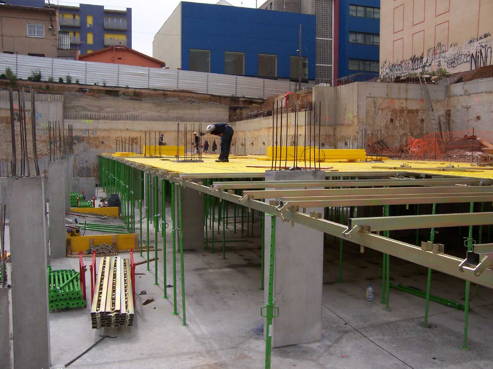
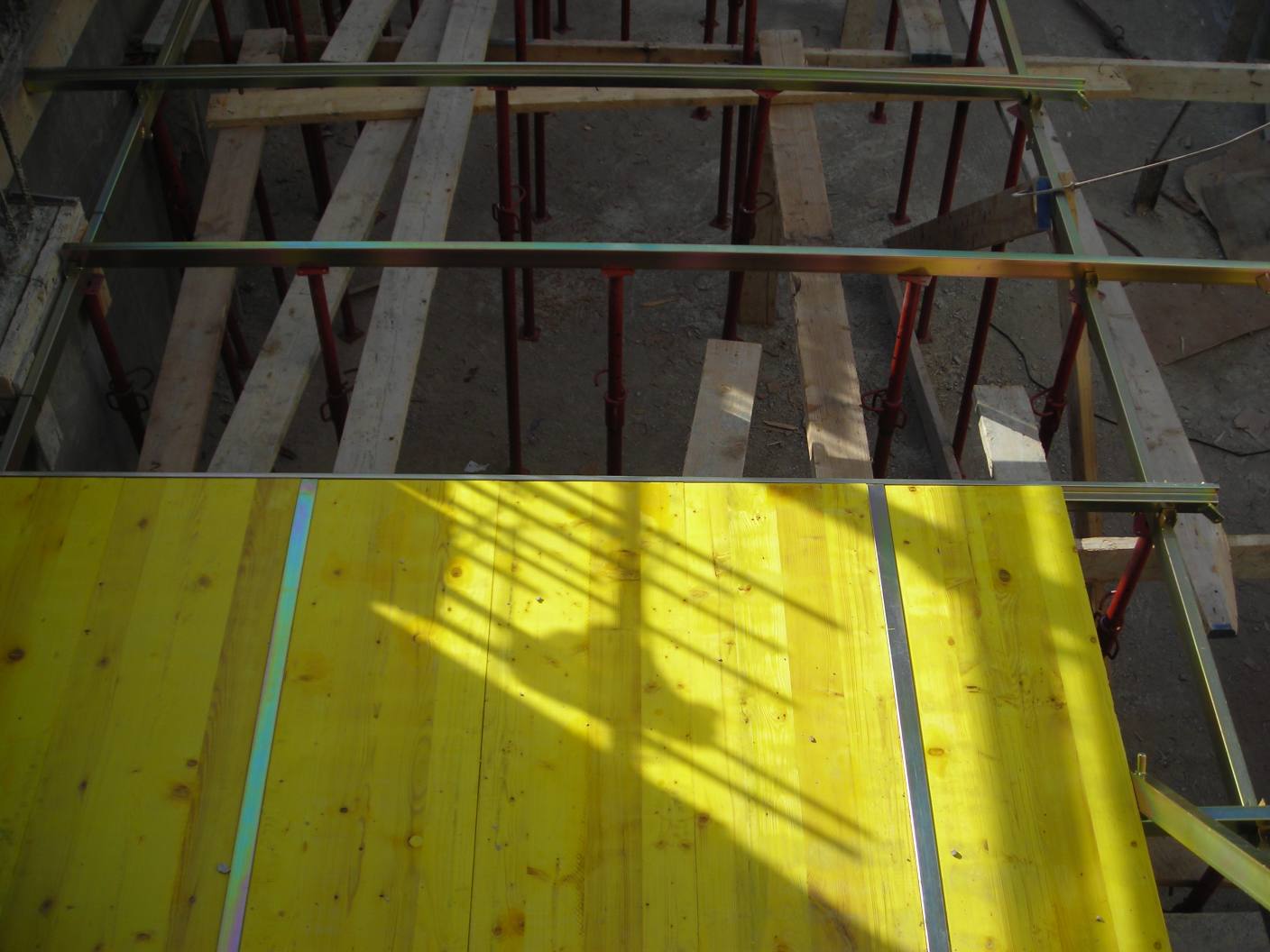
Main Beam System
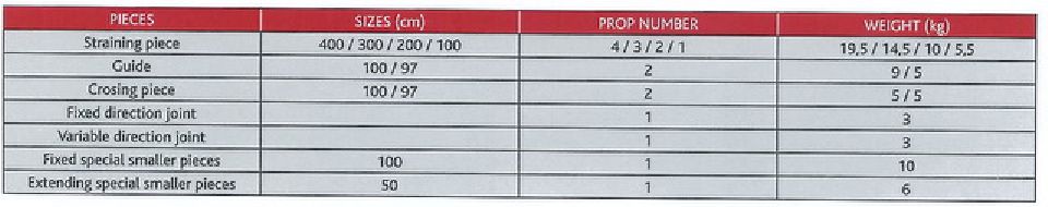
Specially designed system to fit the panels for Main and Edge Beams. It is very easy to assembly and dismantle. Three main parts compose the system: Straining Pieces, Guides and Crossing Pieces. The Straining Piece, with its closing profile, is where we fit the wood panels. The Guide forms the streets and here we will fit the Straining Pieces. The Crossing Pieces will support all the structure after all the plant has been formed, recovering 85% of the element of all the structure, supporting the weight of all the structure. We fit one Crossing Piece every two wood panels. It is recommended depending on sizes to fit panels bracing the ribs between beams to reduce formworks weight. |
|
|
 |
Encofrado de Jácena colgada
El Encofrado de Jácena colgada |
|
|
|
| ATTACHMENTS |
|
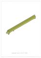 |
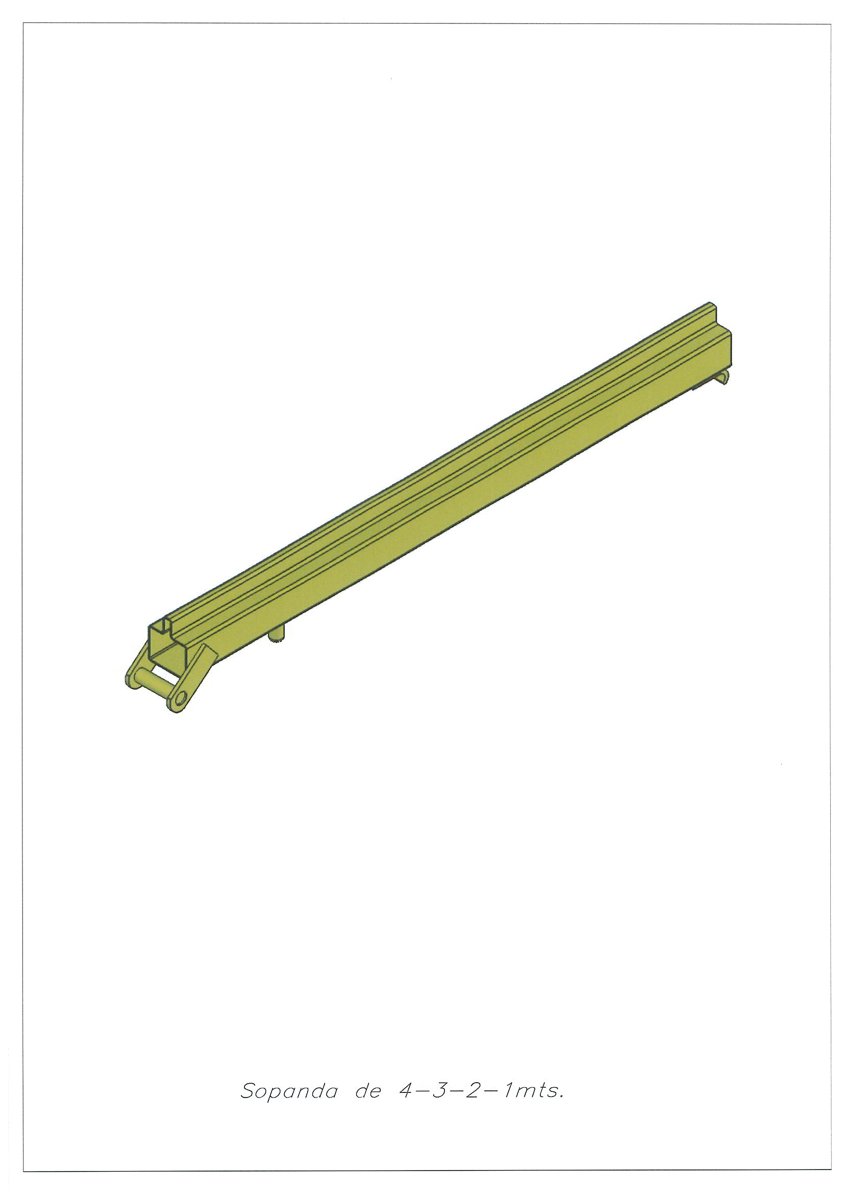
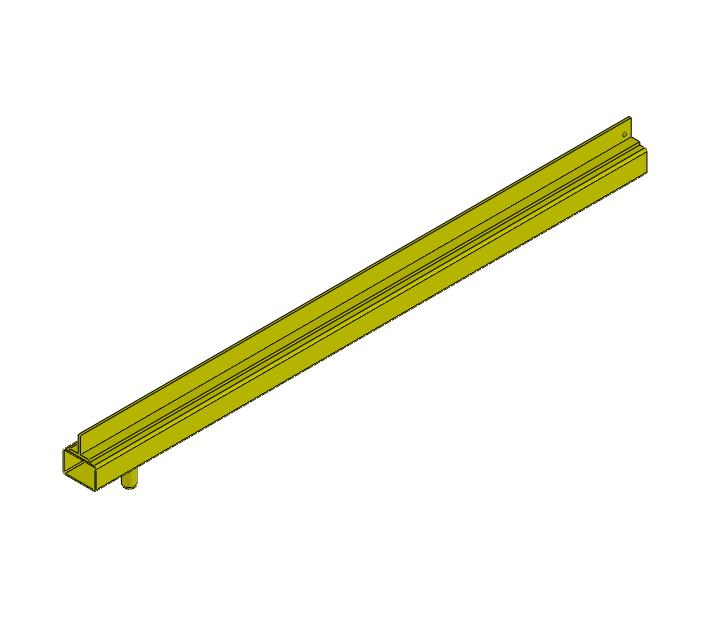
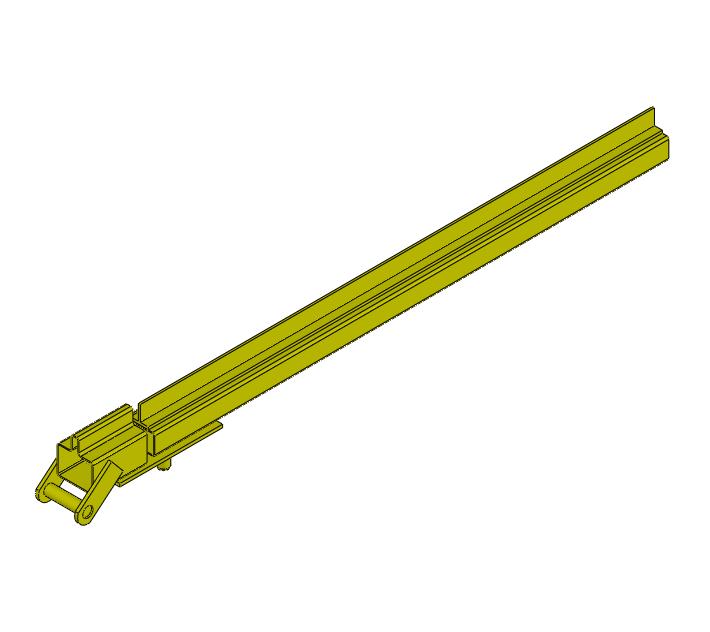
Straining Piece
Use: Floor and Main Beam Systems In the Straining Piece the wood panel is fitted. Its closed profile shape guarantees the necessary resistance on any type of forging. The standard dimensions are 4, 3 , 2 and 1m with projections to fix the props. The assembly bolt and latch are welded to the Straining Piece by its corners. |
|
|
 |
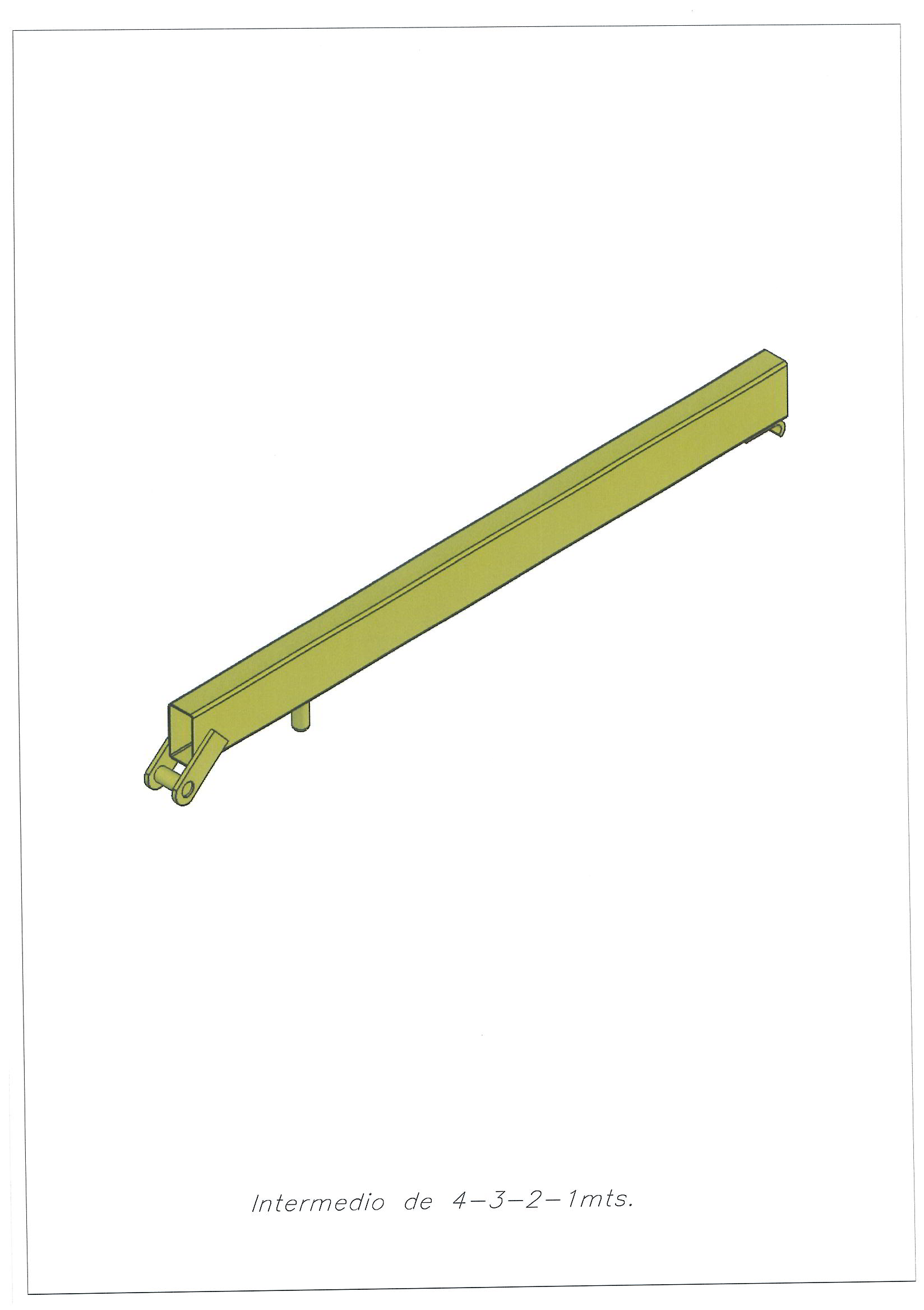
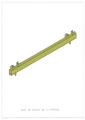
Middle Support Piece
Use: Floor System The Middle Support Piece holds the wood panel. This piece is situated in the middle of the 2m panel equidistantly to both sides Straining Pieces 1m. Its closed profile shape guarantees the necessary resistance on any type of forging. The standard dimensions are 4, 3, 2 and 1m with projections to fix the props. The assembly bolt and latch are welded to the Straining Piece by its corners. |
|
|
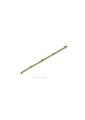 |
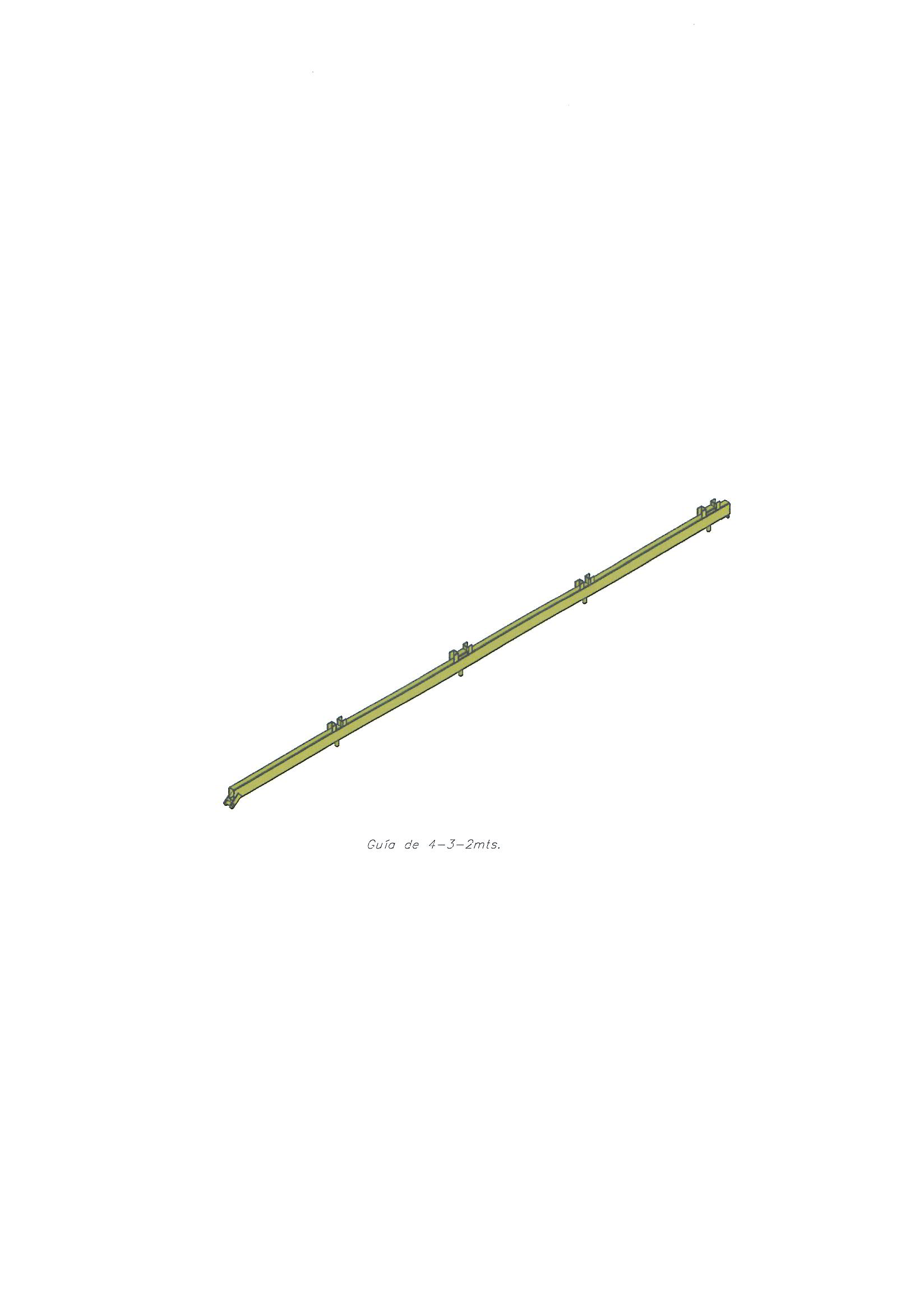
Guide
Use: Floor System The Guide Piece holds Straining Pieces and Middle Support Pieces. Its closed profile shape guarantees the necessary resistance on any type of forging. The standard dimensions are 4, 3, 2 and 1m with projections to fix the props. The 2 and 3m sizes are generally used for finishing, projections and balconies. The assembly bolt and latch are welded to the Straining Piece by its corners (except on the 3 and 2 m.) |
|
|
 |
All Straining Pieces Guide
Use: Floor System This Guide holds Straining Pieces. This type of Guide is applied only when using 1m panels as its fittings are designed to fit just the Straining Piece. Its closed profile shape guarantees the necessary resistance on any type of forging. The standard dimensions are 4, 3, 2 and 1m with projections to fix the props. The 2 and 3m sizes are generally used for finishing, projections and balconies. The assembly bolt and latch are welded to the Straining Piece by its corners (except on the 3 and 2 m.) |
|
|
 |
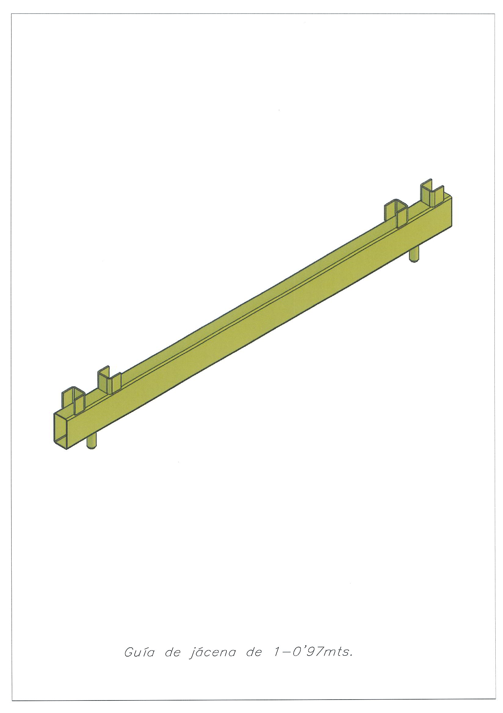
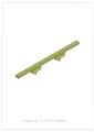
Main Beam Guide
Use: Main Beam System This Guide holds Straining Pieces. Its closed profile shape guarantees the necessary resistance on any type of forging. The standard dimensions 2 and 1m with projections to fix the props. The 2m Guide is only applied on large beams and includes a fitting for a Middle Support Piece in the centre. |
|
|
 |
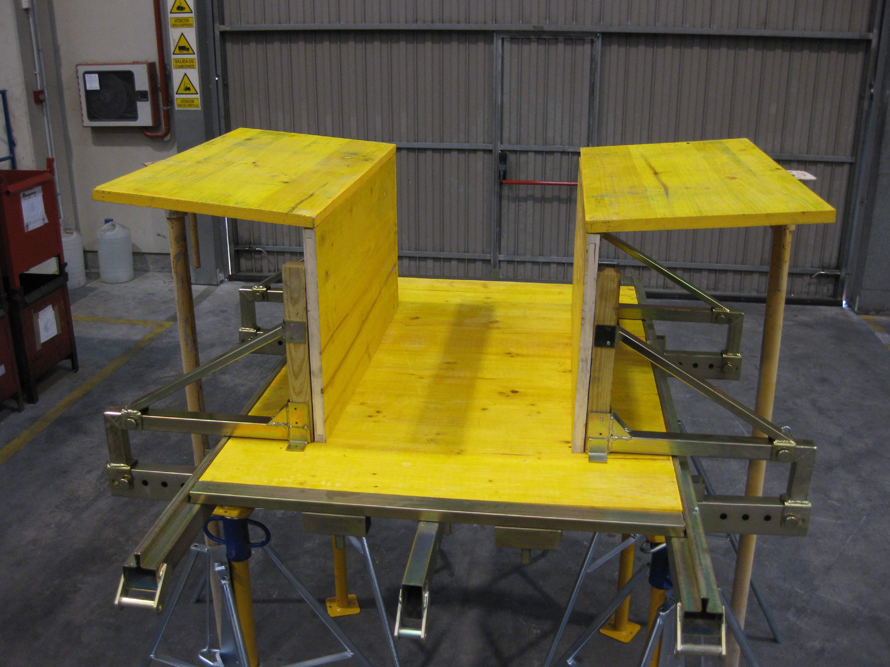
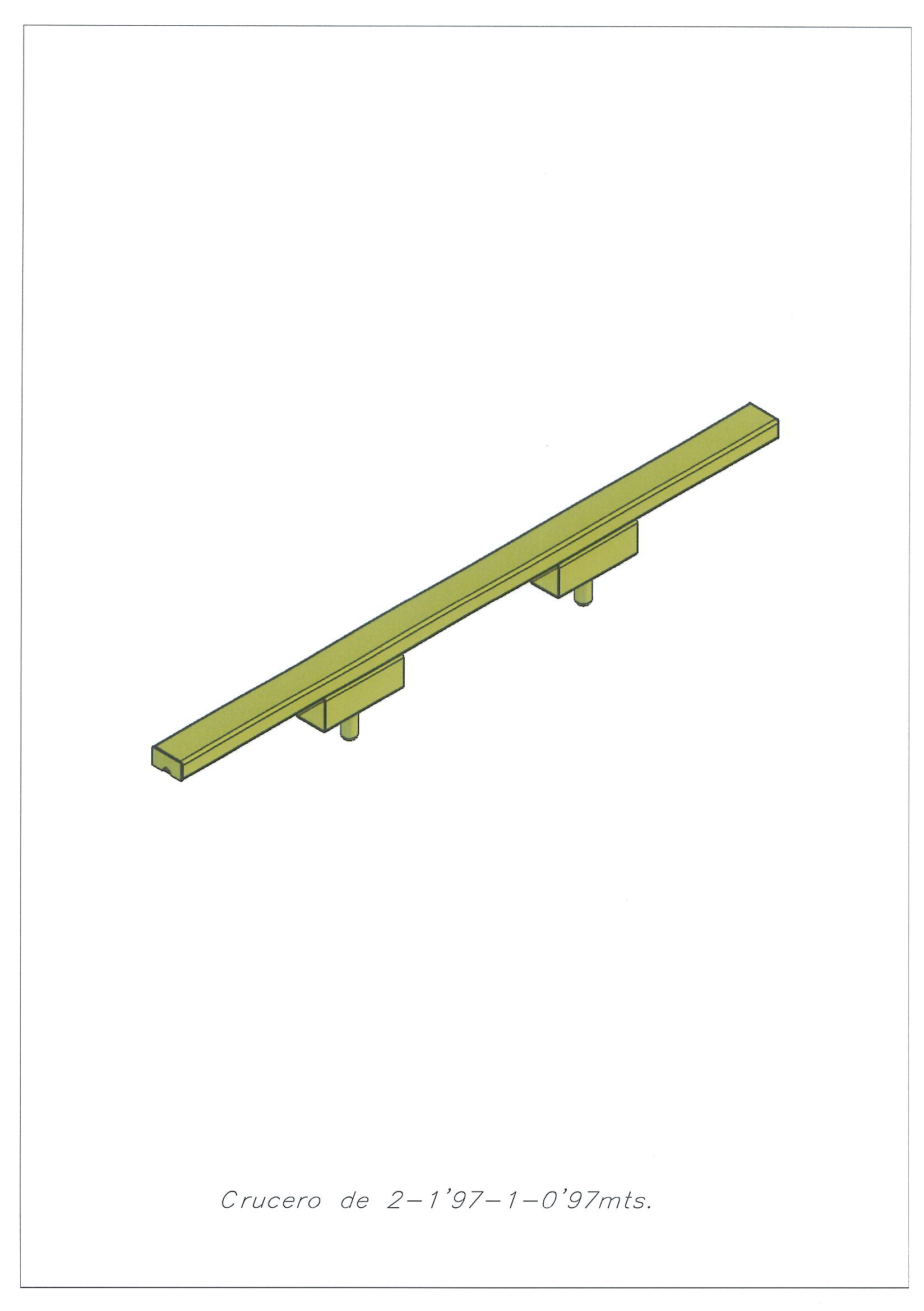
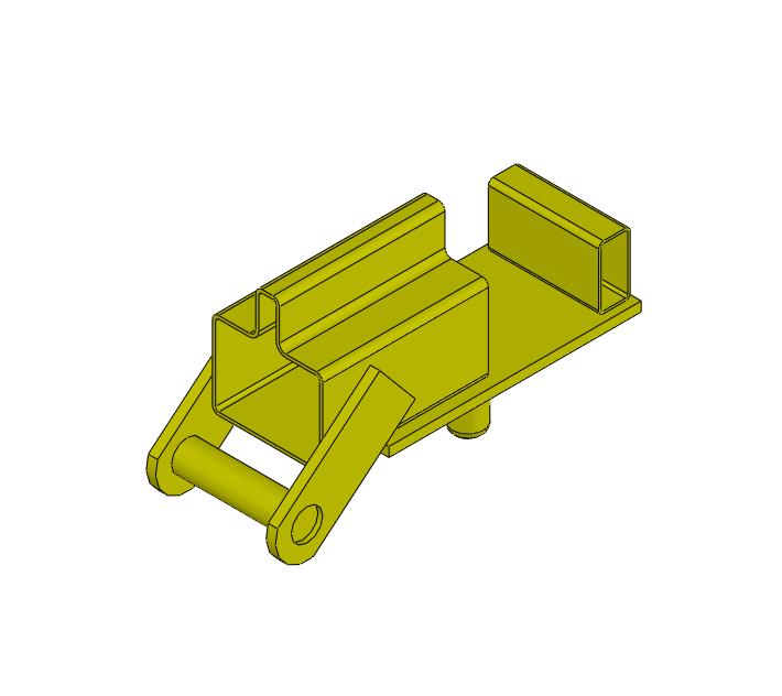
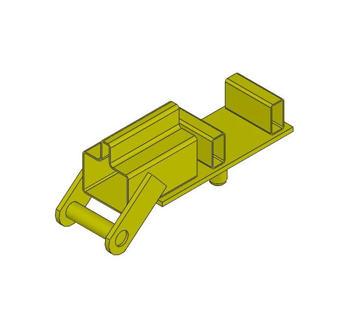
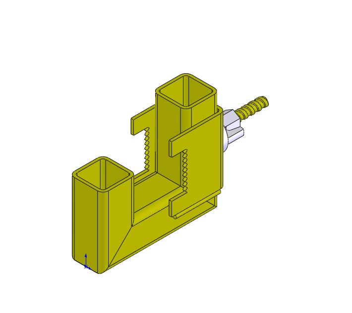
Crossing Piece
Use: Floor (2 and 1,97m) and Main Beam (1 and 0,97m) The Crossing Pieces will support all the structure after all the plant has been formed, recovering 85% of the element of all the structure, supporting the weight of all the structure. |
|
|
|
| ACCESSORIES |
|
| STANDARD MEASURES |
|
MEASURES FLOOR
|
|
MEASURES MAIN BEAM
|
|
|
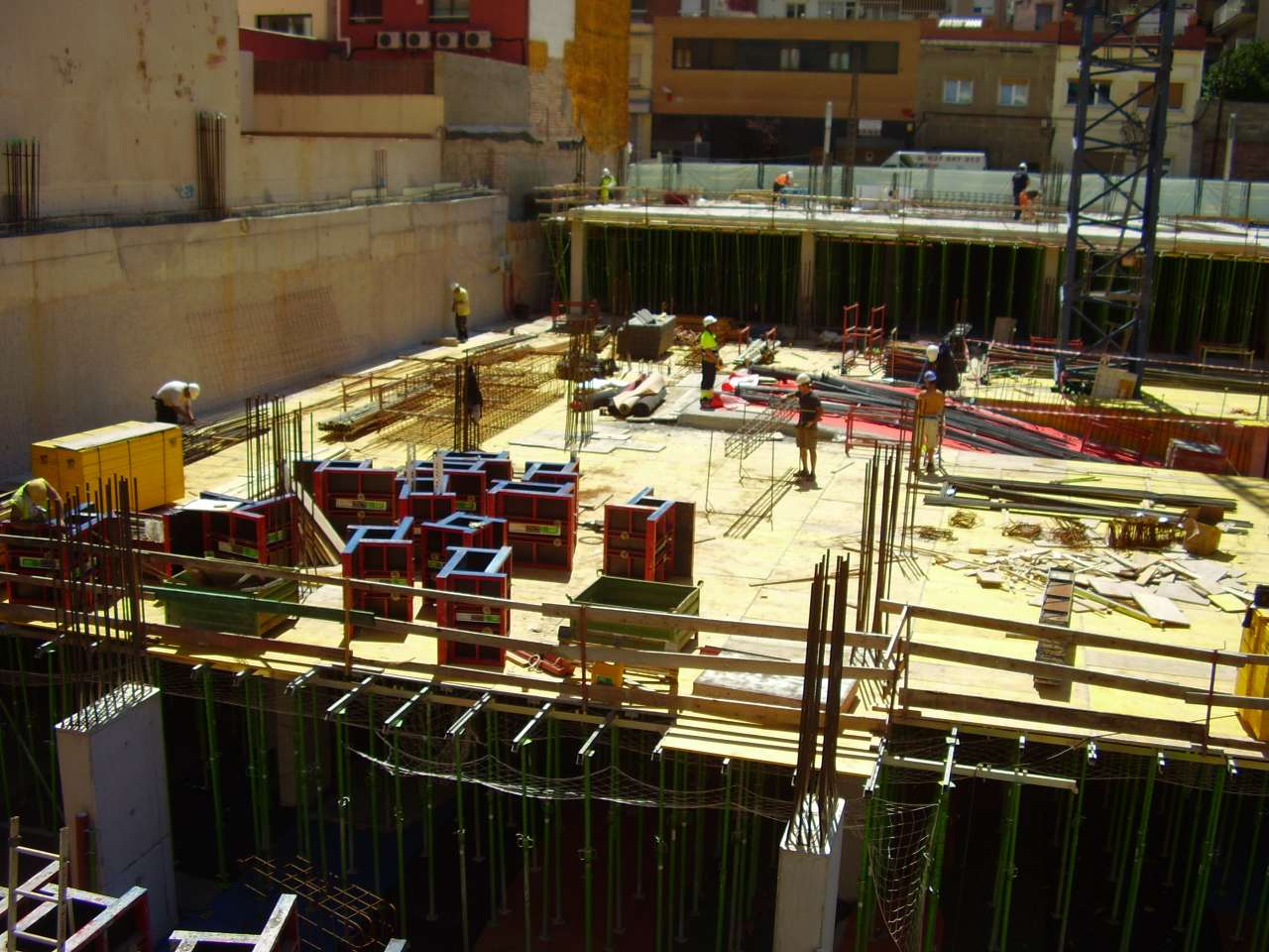
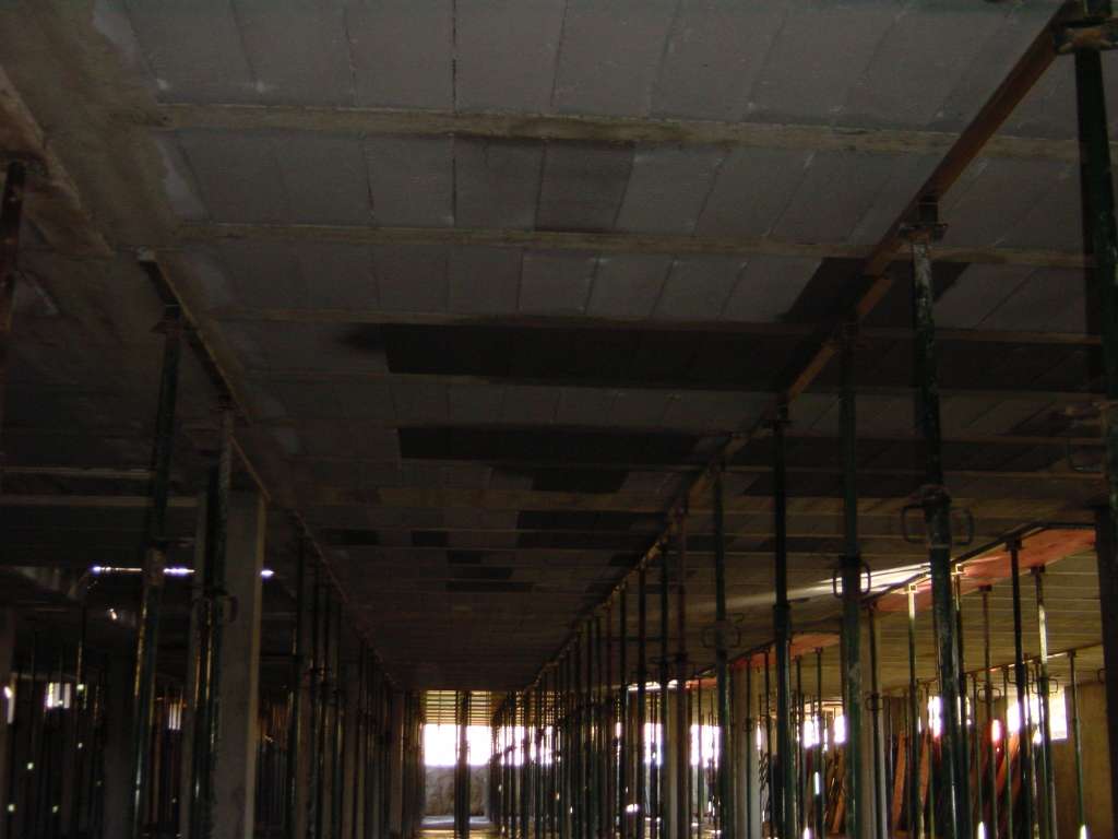
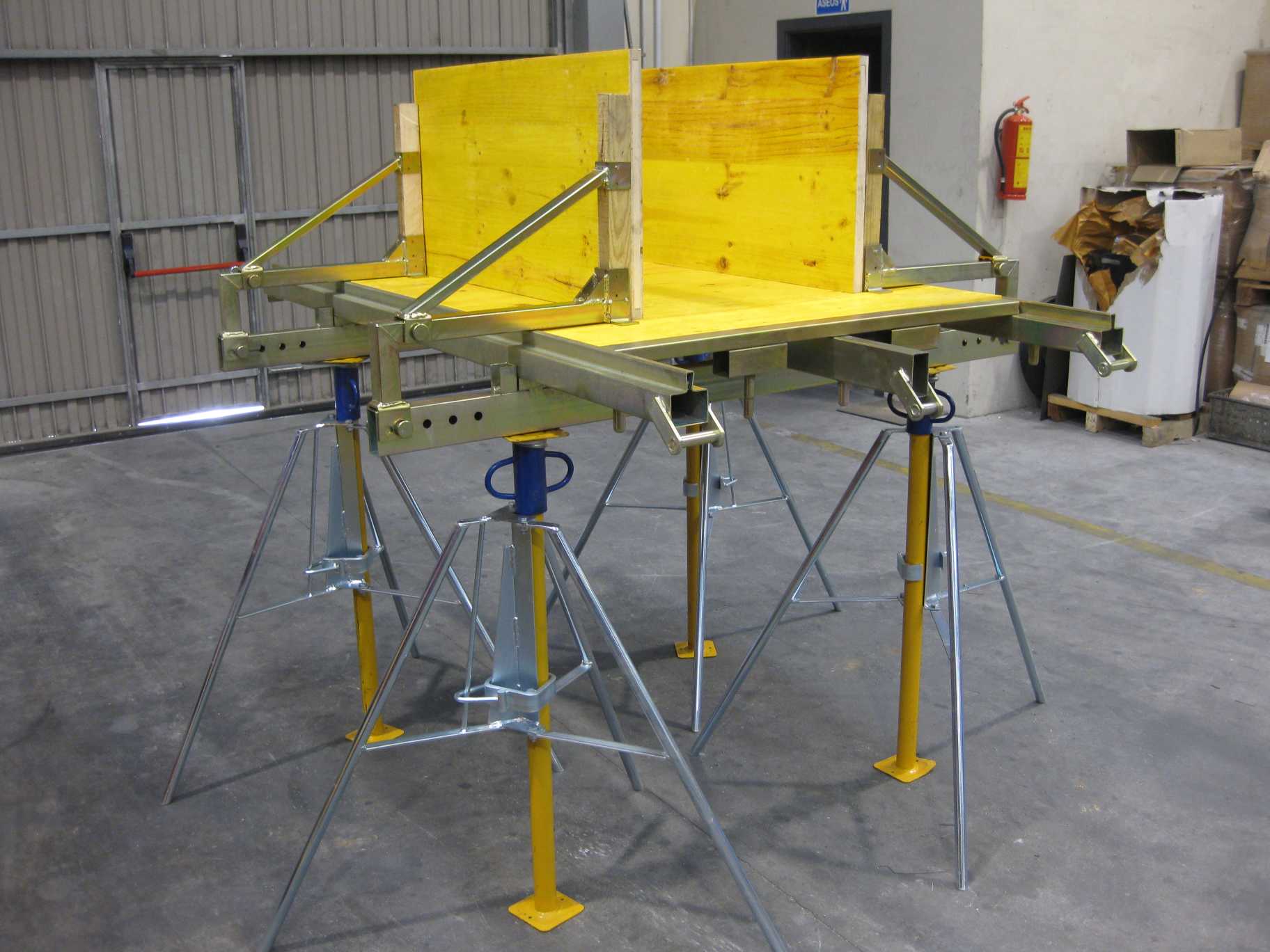
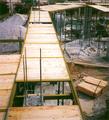
| PHOTOS |
|
| DOWNLOADS |
|
|
 |
|
|
|